| GF07.61-P-3025F | O2-Sondenheizung Function | 10.7.96 |
| ||
| ||
| P07.61-2442-06 |
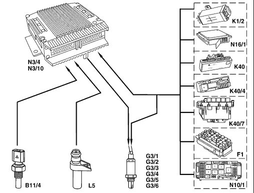
| Shown on Engine 119
B11/4 Coolant temperature sensor F1 Fuse and relay module Model 163 G3/1 O2 sensor downstream of TWC Engine 111, 104  and EURO3/4 and EURO3/4
G3/2 O2 sensor upstream of TWC Engine 111, 104 G3/3 Left O2 sensor upstream of TWC Engine 112, 113, 119, 120 G3/4 Right O2 sensor upstream of TWC Engine 112, 113, 119, 120 G3/5 Left O2 sensor downstream of TWC Engine 112, 113, 119, 120 and EURO3/4
G3/6 Right O2 sensor downstream of TWC Engine 112, 113, 119, 120 and EURO3/4 |
K1/2 Overvoltage protection relay Model 124, 202 up to 7/96 K40 Relay module model 170, 210 up to 2/97 K40/4 Fuse and relay module model 202 as of 8/96, 210 as of 3/97 K40/7 Right fuse and relay module Model 215, 220 (K40/4 in Model 230) L5 Crankshaft position sensor N3/4 HFM-SFI [HFM] control unit N3/10 ME-SFI control unit N10/1 Front SAM control unit with fuse and relay module Model 203 N16/1 Base module, model 129, 140 |
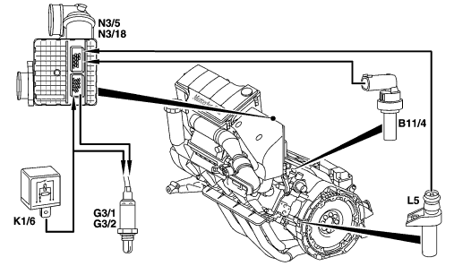
| The engine shown is engine 166
B11/4 Coolant temperature sensor G3/1 O2 sensor downstream of TWC (low emission EURO3/D4) G3/2 O2 sensor upstream of TWC K1/6 Electronics relay L5 Crankshaft position sensor N3/5 ECM control unit (up to 08/01) N3/18 ECM control unit with throttle valve actuator (as of 09/01) |
 | |
| P07.51-0567-05 |
| The purpose of the O2 sensor heater is to rapidly heat up the O2 sensors to their operating temperature while preventing damage to the sensor ceramic as a result of controlled heating power.
The sensor heater is actuated by the engine control unit through ground. The performance of the sensor heater at operating temperature amounts to: 18 w on Engine 104, 111, 119, 120 and 112, 113 with ME2.0 12 w on Engine 166 . 7 W on Engine 137, engine 111EVO and 112, 113 with ME 2.8 as of 06/00 |
The voltage for the sensor heater is supplied by the:
 Overvoltage protection relay model 124, 202 up to 7/96
Relay module, Model 170, Model 210 up to 2/97
Base module, Model 129, 140
Fuse and relay module, model 202 as of 8/96, model 210 as of Overvoltage protection relay model 124, 202 up to 7/96
Relay module, Model 170, Model 210 up to 2/97
Base module, Model 129, 140
Fuse and relay module, model 202 as of 8/96, model 210 as of 3/97, model 163 designation F1 Electronics relay, Model 166
Right fuse and relay module (K40/7), Model 215, 220
Right fuse and relay module (K40/4), Model 230
Front SAM control unit with fuse and relay module
Model 203, 209, 211 |
| The current in the cold state is increased by approximately 4 times. At coolant temperatures below approx. 20 °C and at high engine speeds, the sensor heater is switched off.
Engine 112, 113 The sensor heaters for the left and right O2 sensors are connected in parallel in the ME-SFI control unit. Engine 119 The sensor heaters for the left and right O2 sensors are connected in parallel. ENGINE 120 The sensor heaters for the left and right O2 sensors are assigned to the respective engine control unit. |
Engine 137
Each sensor heater has its own, short-circuit proof output stage in the engine control unit with diagnosis. As a protection for the ceramic, the sensor temperature upstream of TWC is limited to approx. 350 °C in the condensation phase after cold start. After this, the temperature is controlled to approx. 700 °C. An exhaust temperature is determined from various engine operating data for this purpose and the sensor heated accordingly. Different values apply to the O2 sensor heaters downstream of TWC. |
| Motor electronics control unit, location/task/design/function | GF07.61-P-5000F | ||
| O2sensors, location/task/design/function | GF07.04-P-4103F | ||
| Coolant temperature sensor, location/task/design/function | Engine 113, 137 | GF07.04-P-5026A | |
| Crankshaft position sensor, location/task/design/function | ME-SFI fuel injection and ignition system (ME) | GF07.04-P-4116F |