Models 168, 202, 208, 215, 220
Model 203 up to 7/01
Model 210 with engine 111, 112, 113, 605, 606, 611, 612, 613

| GF42.45-P-4500-01B | ESP control module, function | Model 129 with engine 112, 113
Models 168, 202, 208, 215, 220 Model 203 up to 7/01 Model 210 with engine 111, 112, 113, 605, 606, 611, 612, 613 |
|
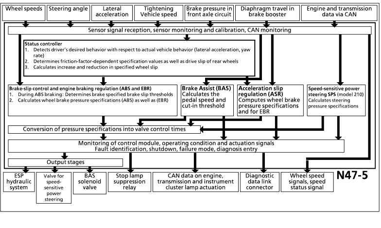 |
The functions of the ESP control module are divided as follows:
 Signal conditioning
Function logic component
Safety circuit
Auxiliary functions Signal conditioning
Function logic component
Safety circuit
Auxiliary functions
Signal conditioning The following input signals are processed by the function logic component for calculations or as information: Calculation of vehicle speed/slip
- Signals from wheel speed sensors Calculation of lateral forces
- Signal from steering angle sensor (models 203, 215, 220 over CAN) - Lateral acceleration sensor signal - Signal from yaw rate sensor Calculation of longitudinal forces
- CAN data on engine torque - CAN data on current gear - Signal from brake pressure sensor |
Information signals (control)
- Signal from stop lamp switch - Signal from parking brake switch (models 203, 215, 220 over CAN) - ESP OFF switch signal (models 203, 215, 220 over CAN) - Signal from BAS release switch - Signal from BAS diaphragm travel sensor Function logic component The conditioned input signals are processed in the logic component and converted into output signals. Wheel speed sensor signals:
The 4 conditioned wheel speed signals are constantly compared with each other and with specified slip thresholds on the front and rear wheels in relation to the speed of the vehicle. This comparison is used to determine the following values and control variables: - Vehicle speed - Acceleration/deceleration - Brake slip (ABS) - Acceleration slip (ASR) - Deceleration slip (EBR) |
| Signal from steering angle sensor
If the vehicle changes direction or is being driven on a curve, this is detected using the signal from the steering angle sensor and on the basis of the different rotational speeds of the front wheels. These two recognition variables in combination with the vehicle speed provide the ESP control module with information on the driver's desired vehicle behavior. Lateral acceleration sensor signal:
The ESP control module uses the signal from the lateral acceleration sensor to determine the lateral forces occurring during cornering. The status controller in the ESP control module can detect whether the vehicle is oversteering from the lateral acceleration signal together with the yaw rate signal. Yaw rate sensor signal:
The ESP control module uses the yaw rate sensor to detect the movements (yaw rate) that the vehicle attempts to make about the vertical axis (e.g. when the vehicle is accelerated). Using the signals from the lateral acceleration sensor and yaw rate sensor, the ESP control module determines the actual handling characteristics of the vehicle. |
CAN data on engine torque:
The ESP control module is informed about the engine torque output by the engine control module via the CAN data bus. In the case of ESP control mode, the function logic component tells the engine control unit to set a reduced engine torque. CAN data on current gear (automatic transmission only):
Via the CAN data bus the function logic component (ESP) is constantly informed about the currently engaged gear by the ETC control module. The current gear is used to calculate the drive forces acting on the drive wheels and for drive torque control. Signal from brake pressure sensor (B34),
Model Series 202 with 111, 605, 611 Engines and Model Series 170, 208 with 111 Engine, Model Series 203 : ESP pressure sensor 1 (B34/1) and ESP pressure sensor 2 (B34/2): The brake pressure sensor(s) detect(s) the brake pressure which is used by the logic component to calculate the wheel brake forces (longitudinal forces). If ESP control becomes necessary, the existing wheel-brake forces (longitudinal forces) are taken into consideration when the cornering forces (lateral forces) are calculated. |
| Signal from brake light switch (S9/1):
When the brake is actuated, signals from the dual contact switch (NO and NC contact) are registered and evaluated by the ESP logic component. This process is terminated immediately if, for example, ASR control becomes active. In the case of ESP control, these information signals are processed in addition to the brake pressure sensor signal. Parking brake switch signal (S12; models 203, 215, 220 over CAN):
If a signal is issued from the parking brake switch, EBR control mode is not permitted. ESP OFF switch signal (S76/6; Model Series 215, 220 through CAN), (Model Series 203; N72/1s1 through CAN):
If a signal is received from the ESP OFF switch, the drive torque control circuit is deactivated and the ESP warning lamp is actuated to shine constantly. BAS release switch signal:
When the BAS release switch is not actuated and the BAS solenoid valve is active at the same time, the brake lamps are prevented from lighting when the brake pedal is not depressed. This is effected by actuation of the stop lamp suppression relay or directly by the control module (model 203, 215, 220). |
BAS diaphragm travel sensor signal
The signal from the BAS diaphragm travel sensor is used to calculate the speed at which the brake pedal is actuated. The brake pedal speed is used as a criterion for BAS actuation. Safety circuit The task of the safety circuit is to identify erroneous signals from the sensors and faults in the control module and in the wiring system. During the control sequence, it monitors actuation of the high-pressure/return pump. The solenoid valves are monitored permanently. If a fault is detected, the system is shut down and the driver is alerted by the lighting of the BAS/ESP indicator lamp (A1e47). In addition, a fault code is stored in the control module. The safety circuit also constantly monitors the battery voltage. If the voltage falls below 10.5 V or exceeds 17.5 V, the system is switched off until the voltage returns to the specified range. |
| Auxiliary functions
Speed-sensitive power steering subfunction The control module uses the ground speed and status signal to calculate the current required to control the speed-sensitive power steering P-valve (Y10). Brake Assist (BAS) sub-function The conditioned input signals are processed in the logic component and a BAS braking sequence is initiated if required (see BAS control module, function). |
Wheel speeds and speed status signal outputs Wheelspeed output: The ESP control unit transmits data on instantaneous wheelspeed to all systems that require a wheelspeed signal for operation.
Wheelspeed status signal output: the ESP control unit transmits the wheelspeed status signal to all systems that require information on current vehicle status (vehicle stationary, in motion, wheelspeed sensor defective).
Indicator lamp actuation The ESP control module receives the signals from the brake lining wear contacts and the parking brake. These signals, together with the signals for the ABS and ESP indicator and warning lamps, are passed on to the instrument cluster via a serial data line. (Via the CAN data line in vehicles with a CAN connection on the instrument cluster.) |